I'm Daanish. A mechanical engineer working at the intersection of design, controls, and robotics.
02 — CONTROL THE PROCESS
Where code meets metal.
A precise path becomes a stream of energy. Motion, material, and control working as one system.
03 — VERIFY THE RESULT
Built. Tested. Refined.
One continuous pass transforms the surface. From the first design decision to a controlled outcome.
Intent →Motion. Material. Performance. A study in controlled transformation.
KINEMATIC STUDY / ASSEMBLEORIGINAL 3D ANIMATION
GEORGIA TECH · MSME
01 Design
02 Control
03 Verify
SCROLL TO TRANSFORM ↓
01 / PROJECT INDEX
Engineering, in practice.
Industrial robotics. Research systems. Mechanical design.
01PROJECT CONCEPT
Redwood Materials · Reno, NV
Mechanical Engineering Intern · May–Aug 2025
Bed Sensor Flange Mount & FANUC Robot Programming
A custom thermal-spray fixture and validated FANUC paths. Built around motor torque, fabrication, and coating quality.
Open project ↗
Bed Sensor Flange Mount & FANUC Robot Programming
Redwood Materials · Reno, NV
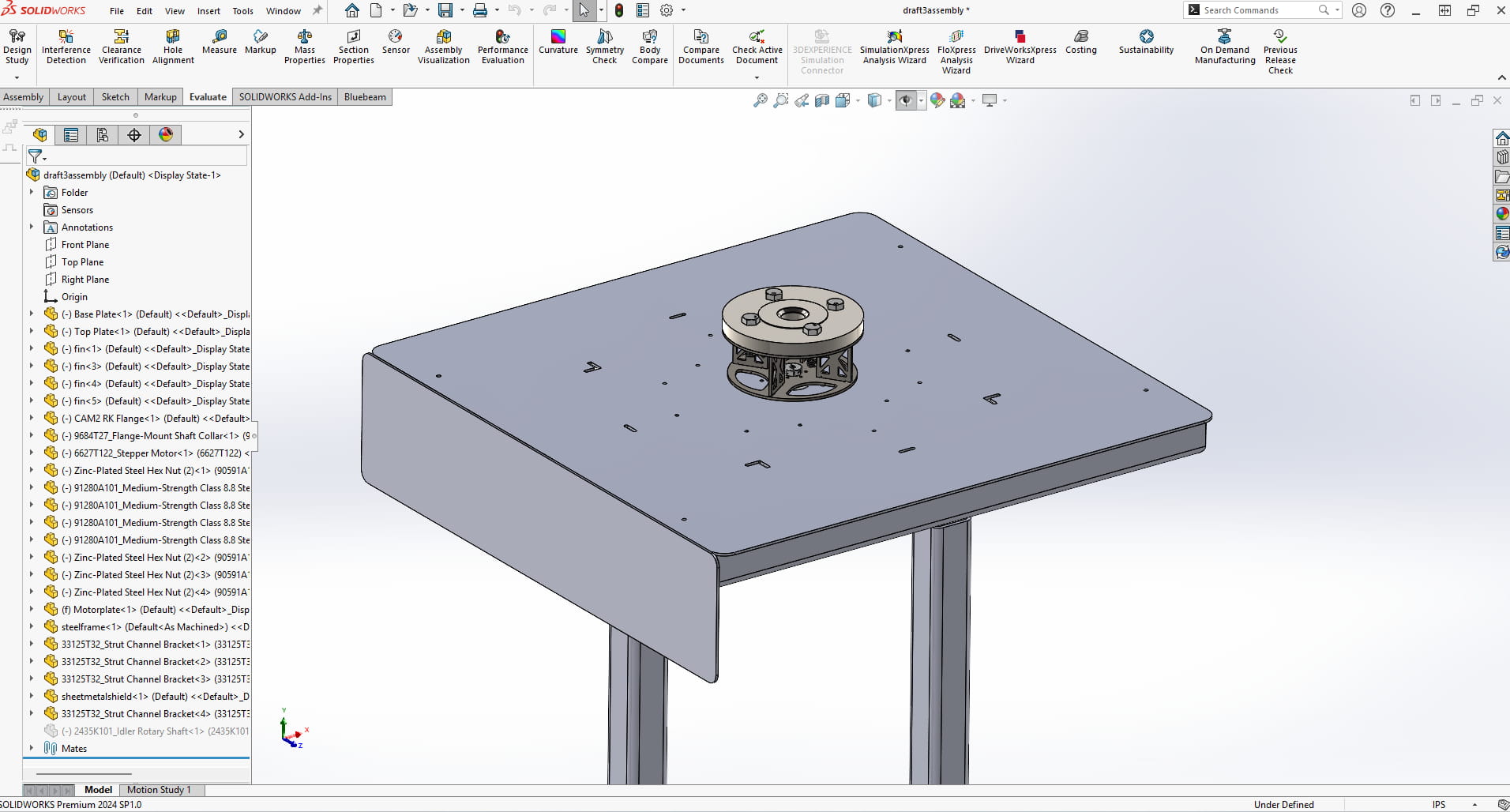
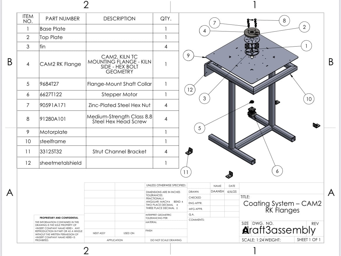
Designed and assembled a custom fixture to spin a bed sensor flange for a thermal spray coating operation. Engineered around real constraints, targeting up to 250 RPM while staying within motor torque limits, selecting 11-gauge mild steel for the rotating section and 2×2 square steel tubing for the fixed stand. Built in tab-and-slot features to simplify welding and assembly, and ran RPM and robot speed calculations across different flange diameters to dial in process parameters.
SolidWorks Assembly — Bed Sensor Mount
2D Assembly Drawing — BOM & Exploded View
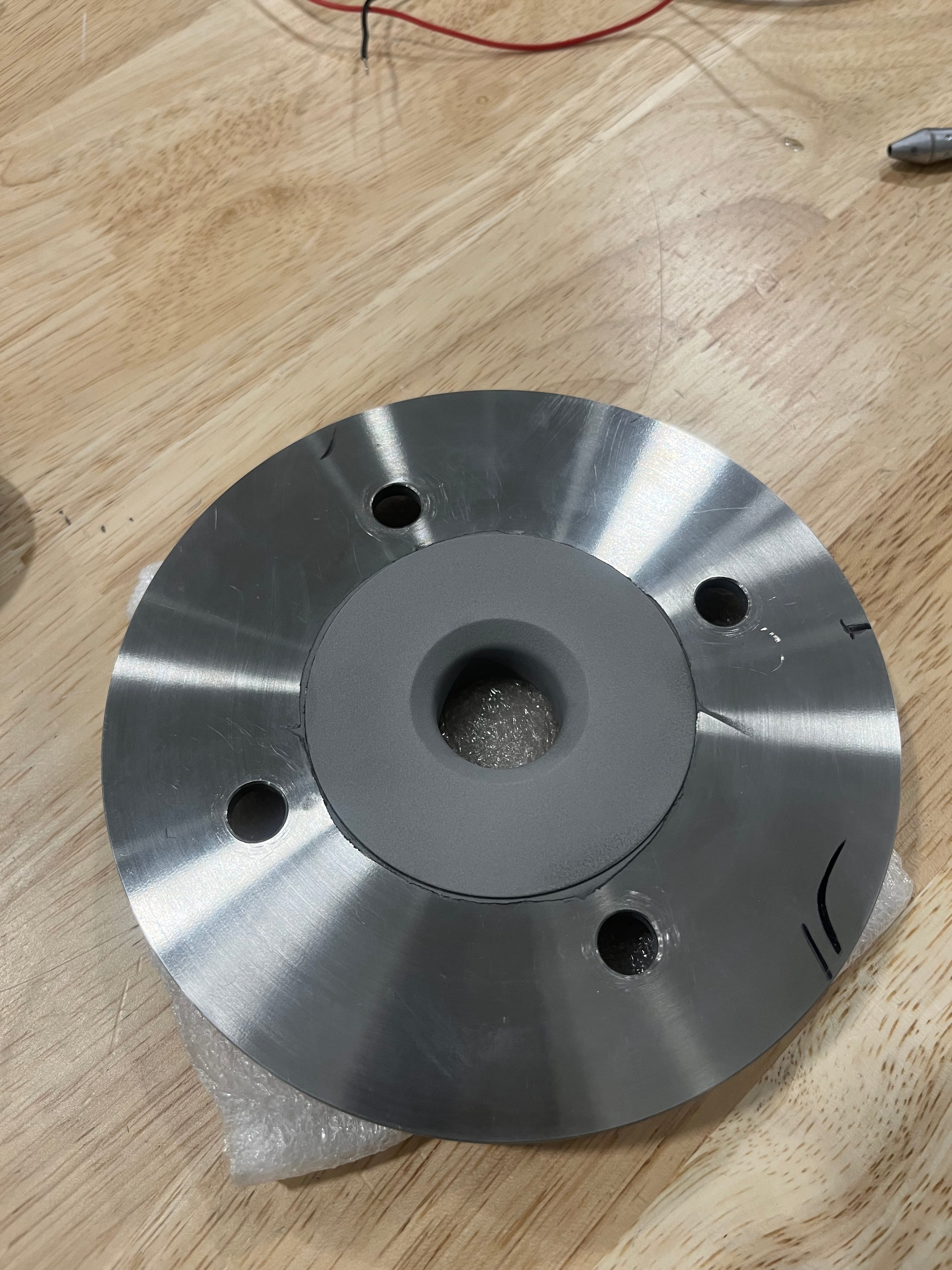
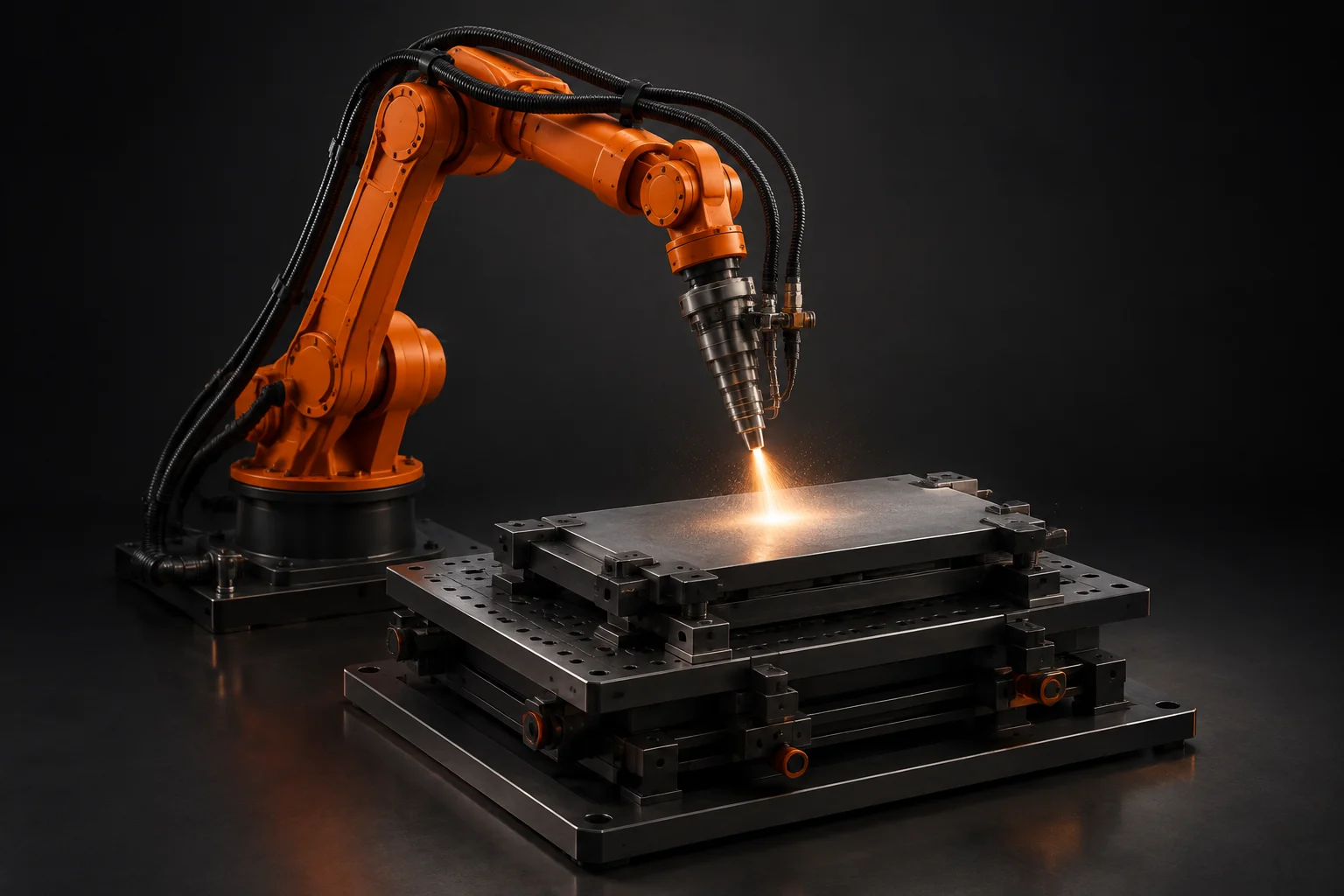
Programmed a FANUC robot via teach pendant to coat both the top surface and inner diameter of the flange, and used FANUC ROBOGUIDE to simulate and validate spray paths. Supported coating quality verification to confirm thickness met target; final coating landed in the 240–320 micron range. Part of a broader HVOF thermal spray operation that improved coating cycle time by ~12%.
FANUC Robot — Coating Plate
FANUC Robot — Coating Flange
Coated Flange — 240–320μm Thickness
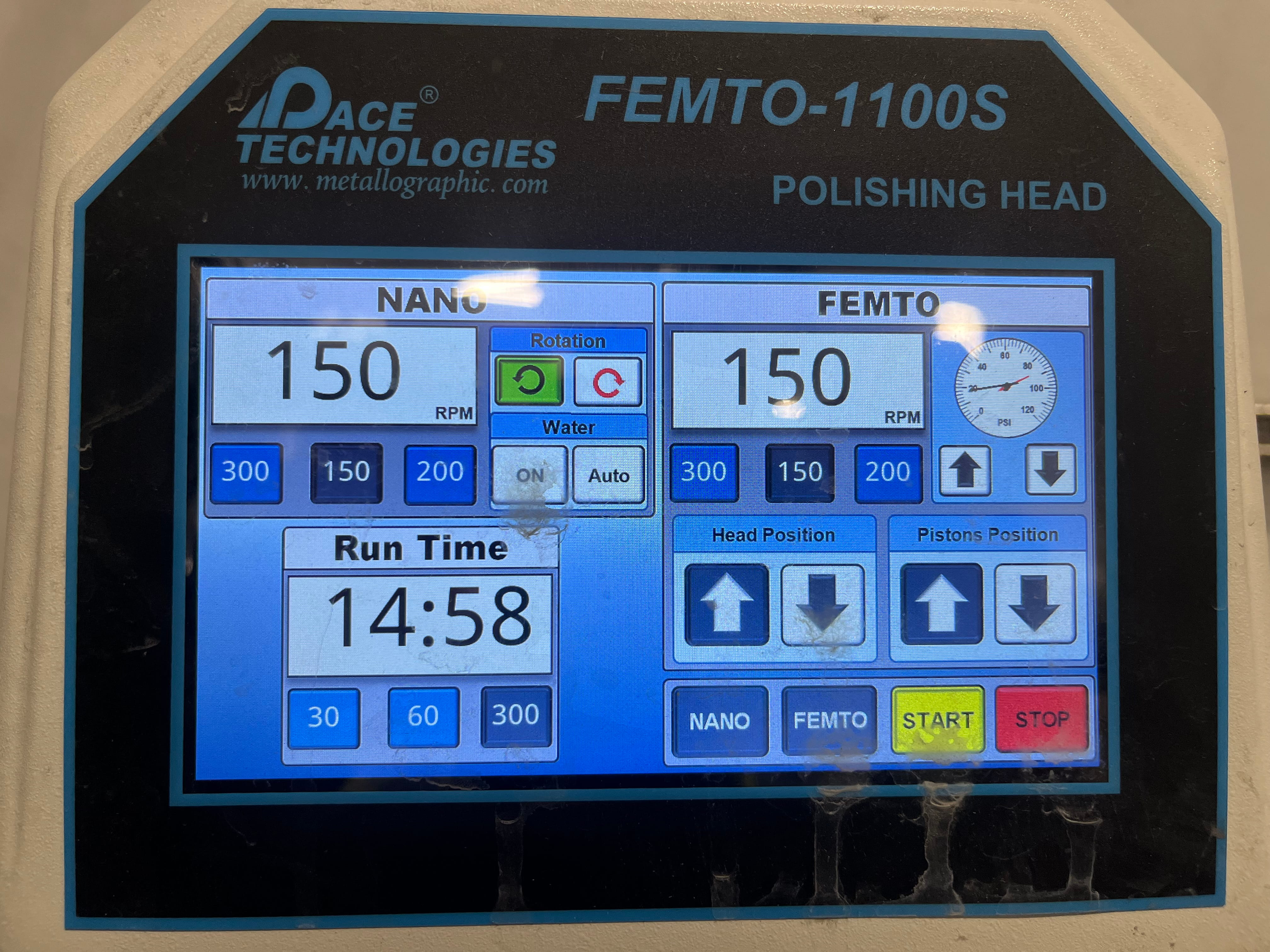
Conducted metallurgy-based testing to verify coating quality, including microhardness, surface roughness, tensile, and adhesion tests, confirming coating thickness in the 200–400 micron range and proper material hardness. Streamlined the testing workflow, cutting total process time from 9 to 7 hours.
Georgia Institute of Technology · ME 4042 · Atlanta, GA
Interactive CAD & CAE · Jan–May 2026
Zipline P2 Delivery Droid — Modelling & FEA
A 60-part Siemens NX reconstruction with a rack-and-pinion delivery mechanism and motor-mount structural analysis.
Open project ↗
Zipline P2 Delivery Droid — Modelling & FEA
Georgia Institute of Technology · ME 4042 · Atlanta, GA
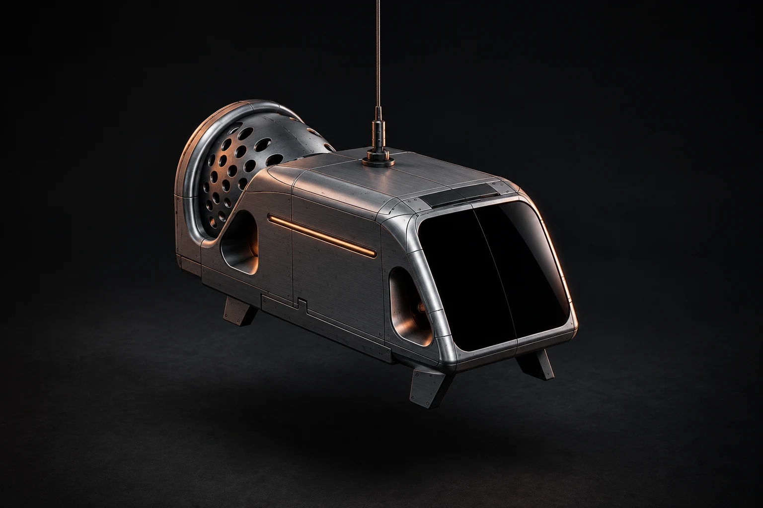
Modelled and analyzed the Zipline P2 delivery droid — the small autonomous sub-vehicle that descends from the main drone to achieve doorstep-level delivery accuracy in urban environments. The droid uses three motors and propellers to counteract wind loads and precisely position itself during descent, and the goal of the project was to accurately replicate its geometry in Siemens NX and perform computational and structural analysis to validate the design against key performance specifications.
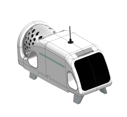
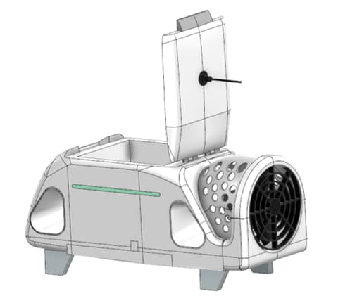
The main body was built from scratch by importing six-sided raster reference images into NX and scaling them to a known bounding box. Bounding curves were generated for half the body and surfaced using Through Curves, Through Curve Meshes, and Studio Surfaces. The resulting half-body sheet was mirrored about the symmetry plane, and all surfaces were sewn into a closed solid. Edge Blend operations were applied along all surface seams to achieve smooth curvature transitions. Following the smooth body creation, Sweep and Extrude subtract operations were used to cut openings for the side propeller assemblies, rear motor bay, light bars, drone feet, front screen, lid, food/medicine compartment, and bay doors — with extruded hinge features added to interface with the lid mechanism.
Full Assembly — Closed Configuration
Full Assembly — Open Lid Configuration
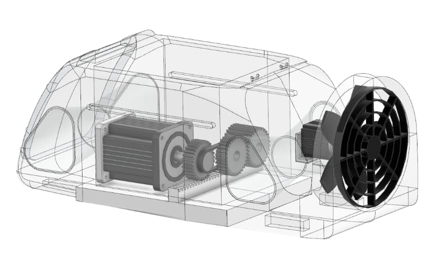
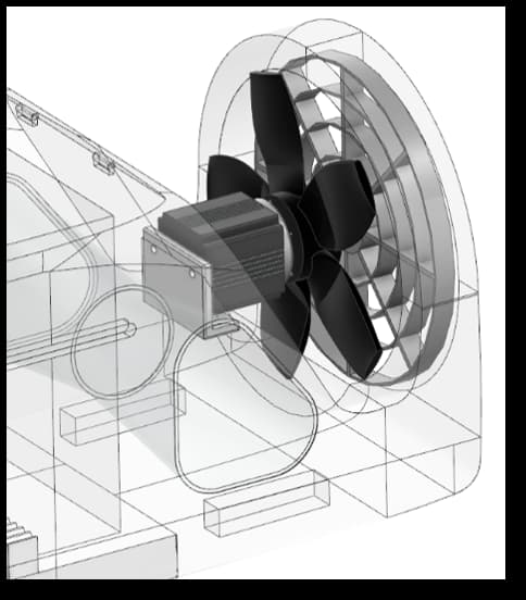
Transparent View — Internal Motor & Bay Door Mechanism
The main propeller sub-assembly required the highest modeling complexity in the project. Each blade was defined by sketching cross-sectional airfoil profiles on a series of offset datum planes along the blade span, capturing the varying chord width and twist angle at each station. A Through-Curves loft was applied through all cross-sectional sketches to generate a smooth, twisted blade surface. A single blade was then patterned in a five-instance circular array about the hub axis. The hub itself was modeled as a cylindrical boss with a tapered bore to receive the motor shaft, united with a short collar extrusion. The propeller cover — a cage-like annular guard — was modeled as a circular extrude with a concentric cutout, with radial structural bars patterned circumferentially from a central hub ring to the outer rim. The mounting bracket was modeled as an L-shaped extrusion with edge blends at the internal corner to reduce stress concentration, with bolt patterns on both faces for attachment to the main body and motor rear face.
Main Propeller Sub-Assembly — Twisted Blade Geometry
The bay door mechanism translates rotational motor output into simultaneous lateral displacement of both delivery bay door panels. The door panels were derived directly from the main body solid using an Extrude subtraction, ensuring geometric consistency between the panel outer faces and the body opening with no fit tolerance issues. Integral rack features were extruded from the inner face of each panel, with trapezoidal gear teeth applied as a patterned extrude cut. A pinion gear was modeled with a circular tooth array and a central through-hole to receive the motor shaft. In the sub-assembly, revolute and translational joints were defined at the shaft axis and panel sliding axes respectively, and a rack-and-pinion motion coupling was applied to enforce equal and opposite panel displacement for a given pinion rotation angle.
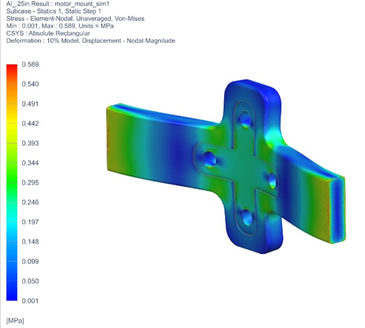
A static structural FEA was performed on the cross-shaped motor mount using Simcenter NX with the Nastran SOL 101 Linear Statics solver. The geometry was meshed with CTETRA(10) 10-node quadratic tetrahedral elements at a global size of 1mm, with local refinement at bolt holes and fillet transitions. Both arm end faces were fully constrained to replicate bolted attachment to the main body, and a 5N uniform pressure was applied to the central motor pocket face in the negative Z direction — consistent with gravitational and dynamic thrust loading. The baseline Aluminum 6061 result at 0.25 inch thickness yielded a maximum von Mises stress of 0.589 MPa against a yield strength of 270 MPa, giving a safety factor of approximately 458. Maximum nodal displacement was 9.412×10⁻⁴ mm, confirming the part operates fully within the elastic regime with negligible deformation. A parametric study was then conducted varying material (Aluminum 6061, Nylon, Titanium Ti-6Al-4V) and arm thickness (0.125, 0.25, 0.375 inches), with results showing that stress is geometry-driven and thickness-dependent, while material selection is governed by stiffness and weight rather than structural necessity.
Motor Mount FEA — Von Mises Stress Distribution (Al 6061, 0.25in, Max: 0.589 MPa)
Designed, printed, and tested a mass exchanger that increased relative humidity from 25.7% to 96.7%.
Open project ↗
LCST Desalination Loop — Mass Exchanger Design
Water–Energy Research Lab · Georgia Tech
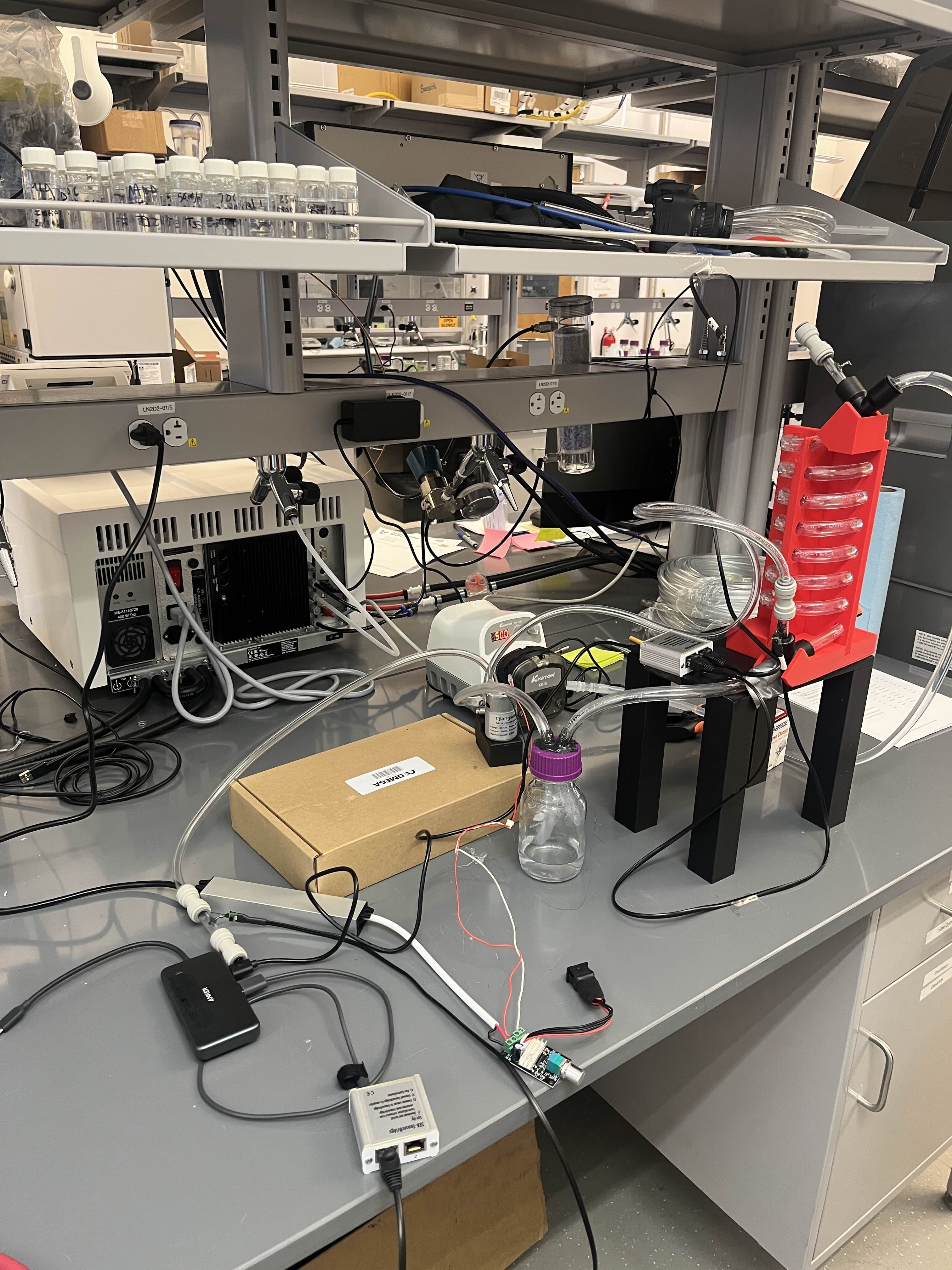
Designed and 3D printed mass exchanger components for a Single Stage LCST (Lower Critical Solution Temperature) desalination loop — a thermally-driven process that separates water from brine using a polymer solution that phase-shifts at a critical temperature. The system cycles brine through warm solution (WS) and water recovery (WR) stages, with air pumps driving humid air across mass exchanger beds while humidity (RH), temperature (T), and flow (F) sensors monitor conditions at each node.
Single Stage LCST Process Diagram — Water–Energy Research Lab, Georgia Tech
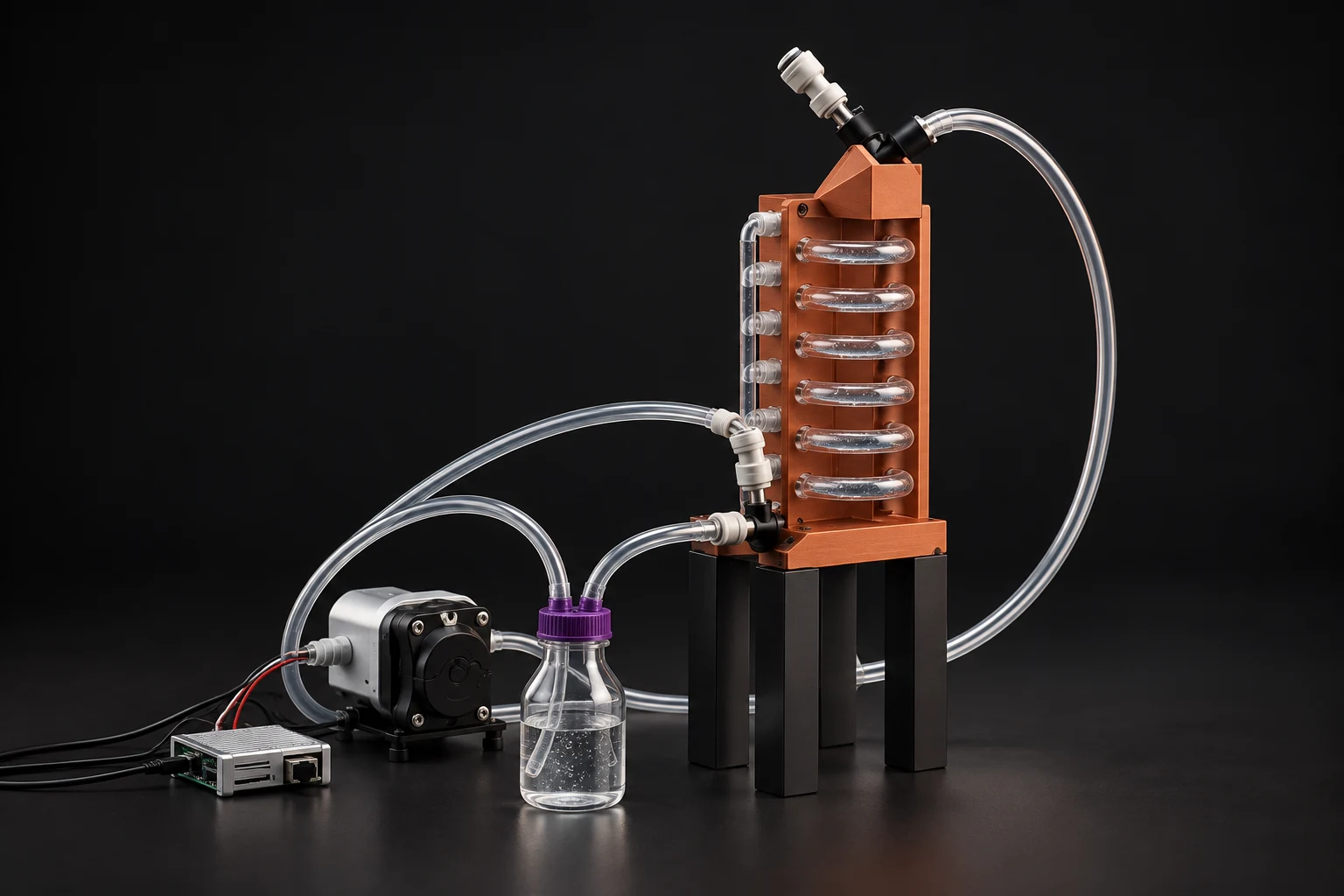
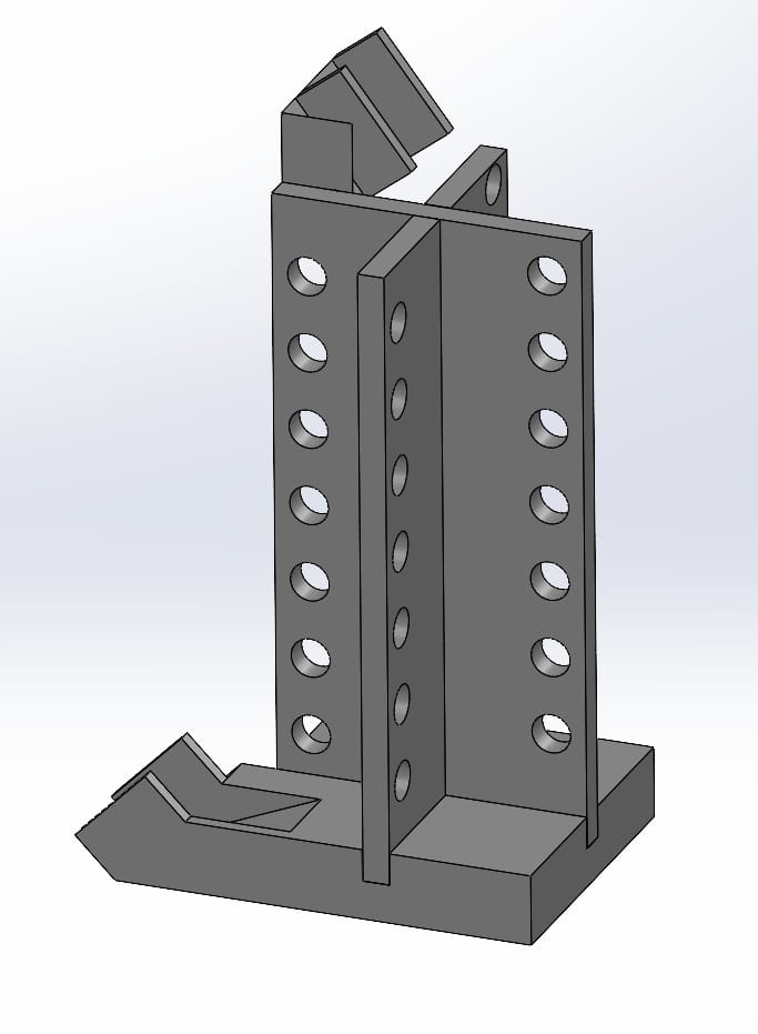
Using SolidWorks, designed detailed CAD models of the mass exchanger components and integrated mounting features for humidity and pressure sensors, control valves, a motor, and a water pump. All components were 3D printed in-house and assembled into a functional test loop. Used Sensirion sensors for real-time humidity and temperature data acquisition throughout testing.
SolidWorks CAD — Mass Exchanger Components
Physical Test Setup — Assembled Loop
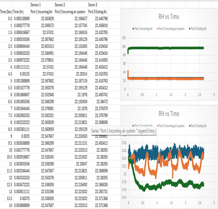
Built and tested multiple configurations of the mass exchanger to evaluate desalination performance, mass exchange efficiency, and leakage control under varying conditions. Each configuration informed design iterations, adjusting geometry, seal interfaces, and flow paths, to progressively improve system performance.
Live System — Flow Test
The final configuration achieved a relative humidity increase from 25.7% to 96.7%, validating the mass exchanger's ability to drive effective moisture transfer across the loop.
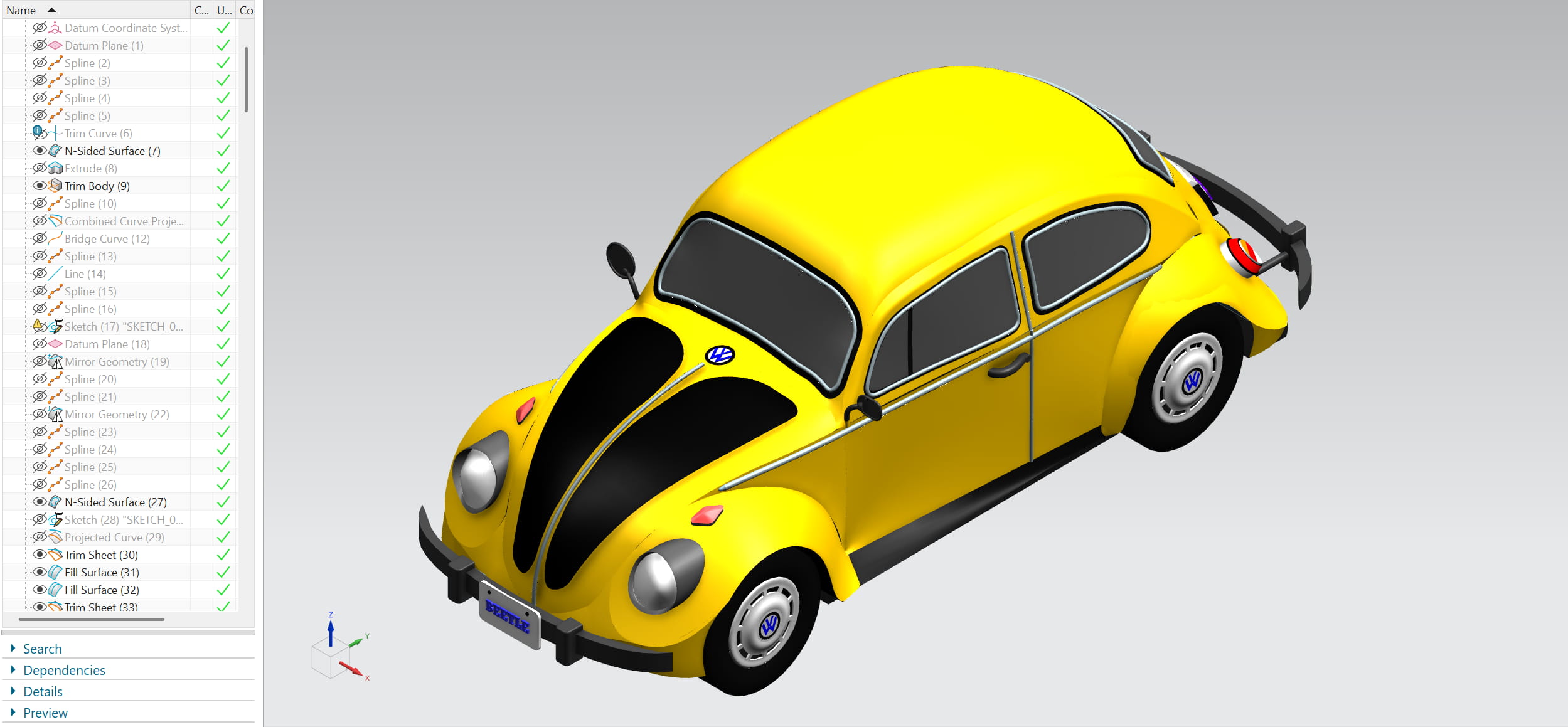
Classic VW Beetle — Surface Modeling in Siemens NX
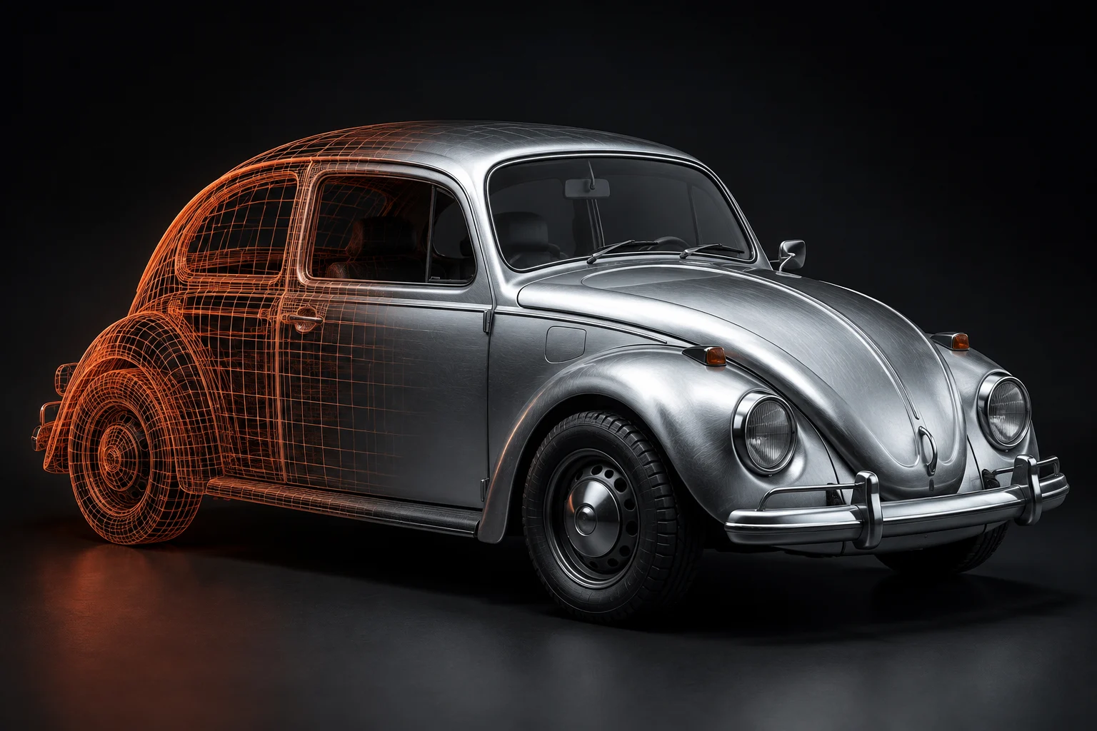
A complete Volkswagen Beetle model, built from parametric splines with G2 surface continuity.
Open project ↗
Classic VW Beetle — Surface Modeling in Siemens NX
Georgia Institute of Technology · ME 4042
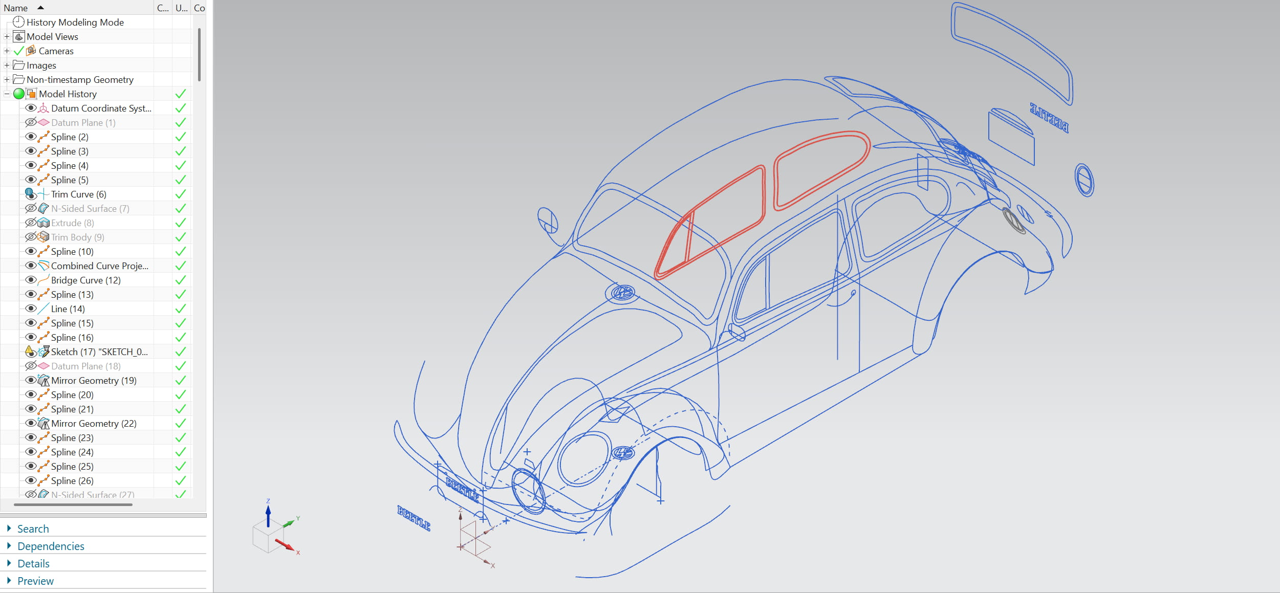
Designed a full 3D model of a classic Volkswagen Beetle in Siemens NX, starting from scratch using spline-based wireframe construction and building up to a complete solid body assembly. The project required generating all geometry from parametric curves — no imported bodies — forcing every surface patch, blend, and transition to be explicitly defined and modifiable.
Spline Wireframe & Curves — Body Profile Construction
Final Rendered Model — Fully Surfaced Solid Body
Surfaces were generated from the spline network using N-Sided Surface, Through Curve Mesh, Ruled, and Fill Surface operations. Through Curve Mesh was critical for the roof and hood panels; by defining primary and cross curves simultaneously, curvature-continuous G2 surface patches were achieved across all major body sections. Interior curves were used within UV orientation settings to control surface shape without introducing additional boundary constraints.
Achieving G2 continuity across the hood, roof, and door panels was a core requirement, enforced by carefully matching tangent direction and curvature magnitude at all shared edges between adjacent patches. Edge Blend operations were applied throughout to eliminate sharp transitions, with individual segment blending used at complex corners where chain blending caused failures. Additional features including bumpers, headlights, door trim lines, window frames, wheel hubs, and axles were modeled beyond the basic requirements.
Georgia Institute of Technology · VIP Program · Atlanta, GA
VIP Research Program · Jan 2025 – Present
Tethered UAV Relay System — Better Place Drones
Two payload-mount concepts and tether-system research for an X8 octocopter communication relay.
Open project ↗
Tethered UAV Relay System — Better Place Drones
Georgia Institute of Technology · VIP Program · Atlanta, GA
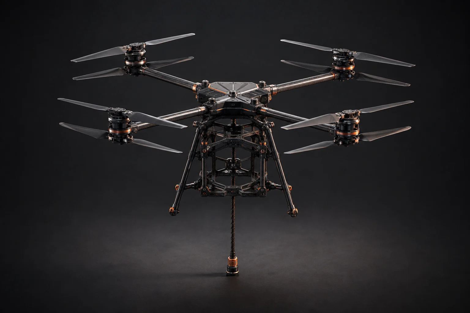
Contributing to the Tethered Relay Development subteam of the Better Place Drones VIP program, focused on enabling persistent aerial communication relay using a tethered X8 octocopter UAV. The tethered configuration eliminates battery endurance constraints by supplying continuous power via a grounded tether, allowing indefinite hover time for relay operations. Work spans from system-level component procurement research through mechanical design and fabrication of custom payload mounting assemblies.
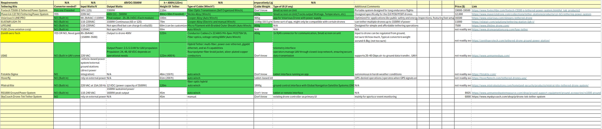
Conducted a structured market survey of commercially available tethered power systems to identify viable off-the-shelf solutions for the X8 platform. Evaluated systems across key parameters including converter requirement, input voltage range, continuous output wattage, tether height and cable type, cable weight per unit length, UI/control interface, and unit cost. Systems assessed included the Fotokite T3500-S, Maverick C2J TK3, Volarous V-LINE PRO, ELISTAIR LIGH-T4, Zenith Aero Tech, USAS, Fotokite Sigma, Hoverfly, Mistral Kite, RS3000 Ground Power System, and SkyCoach Drone-Tek — spanning converter topologies from 48VDC/2500W to vehicle-based power systems, and tether lengths from 45m to 400ft. Key selection criteria included compatibility with 48VDC/2500W input requirements, tether height above 400ft (122m), auto-winch capability, and cable weight below 500g for flight budget compliance.
Tether Kit Procurement Research — Comparative System Analysis Matrix
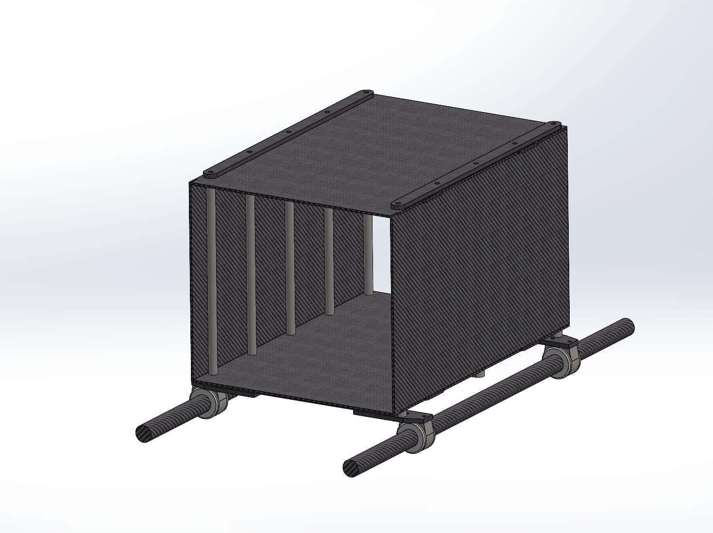
Designed and modeled two iterations of a battery and payload mount assembly for the X8 UAV in SolidWorks, sized to house onboard fuel tanks, electronics bays, and structural attachment interfaces. The first configuration is a rectilinear carbon fiber composite enclosure — an open-frame box structure with internal vertical ribs for component compartmentalization, mounted on dual lateral threaded rod rails with nut-and-clamp fastening for positional adjustability along the airframe. Panel geometry was designed for sheet material fabrication with bolted corner extrusions.
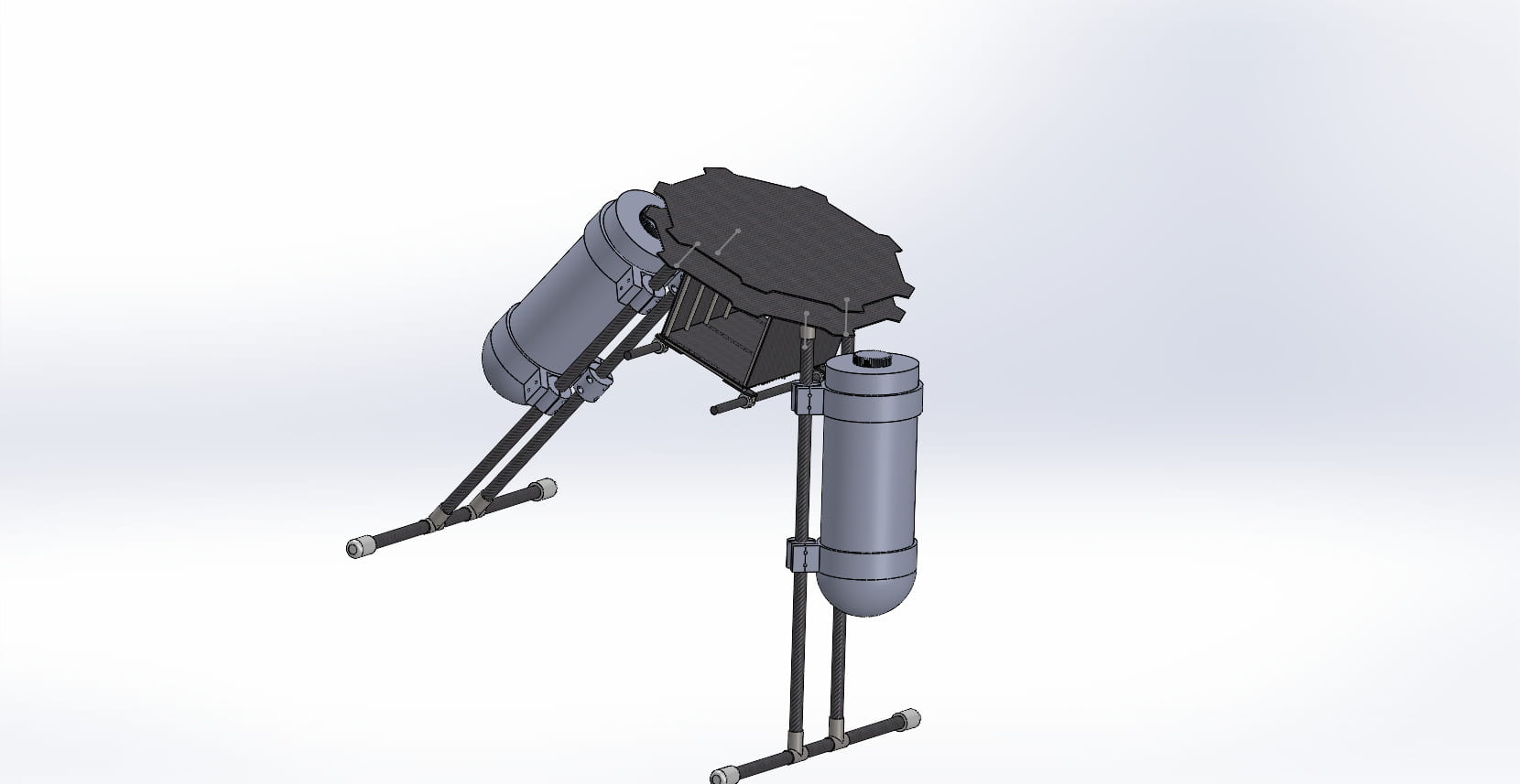
The second configuration is a cantilevered asymmetric mount integrating two cylindrical pressure/fuel tanks — one forward-mounted at an angled orientation and one vertically suspended below the frame — connected via carbon fiber tube struts with threaded rod terminal fittings. The irregular geometry was intentionally designed to offset the center of mass for balance correction relative to the UAV's existing payload distribution. Both designs account for mass budget constraints, structural rigidity under flight loads, and accessibility for field servicing.
Design 1 — Carbon Fiber Box Enclosure with Rail Mount
Design 2 — Asymmetric Cantilevered Tank Mount Assembly
X8
UAV Platform
11+
Systems Evaluated
2
Mount Designs
48VDC
Target Power Input
SolidWorksUAV SystemsTethered DronePayload Mount DesignCarbon Fiber StructureSystems IntegrationProcurement ResearchMass Budget AnalysisStructural DesignVIP Program
06PROJECT CONCEPT
Georgia Institute of Technology · Atlanta, GA
CAD Design Project · 2022
Drug Delivery Drone — Concept & System Design
A fully constrained SolidWorks assembly integrating propeller guards, electronics, payload storage, and landing gear.
Open project ↗
Drug Delivery Drone — Concept & System Design
Georgia Institute of Technology · Atlanta, GA
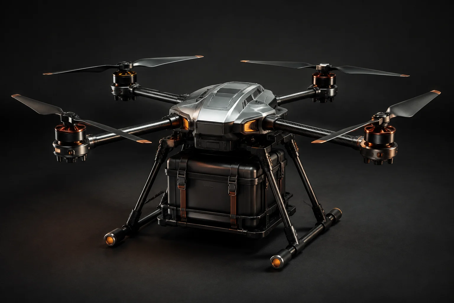
Developed a full concept and system design for a real-world application: an autonomous drug delivery drone. The design objective was to produce a complete, manufacturable assembly within a fixed timeline — from individual components through to a final integrated model.
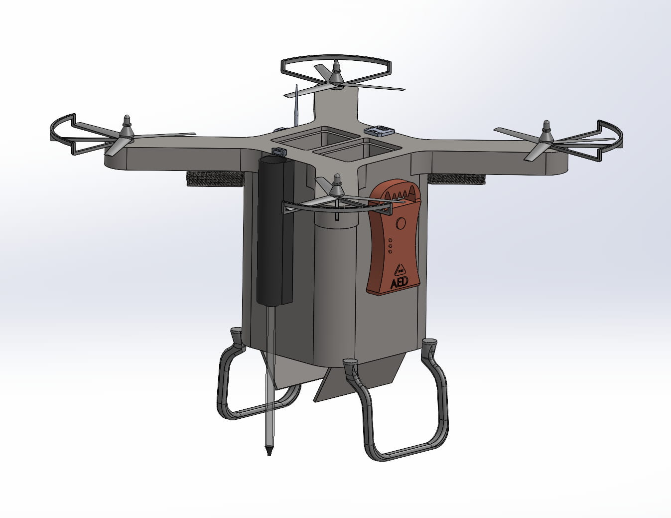
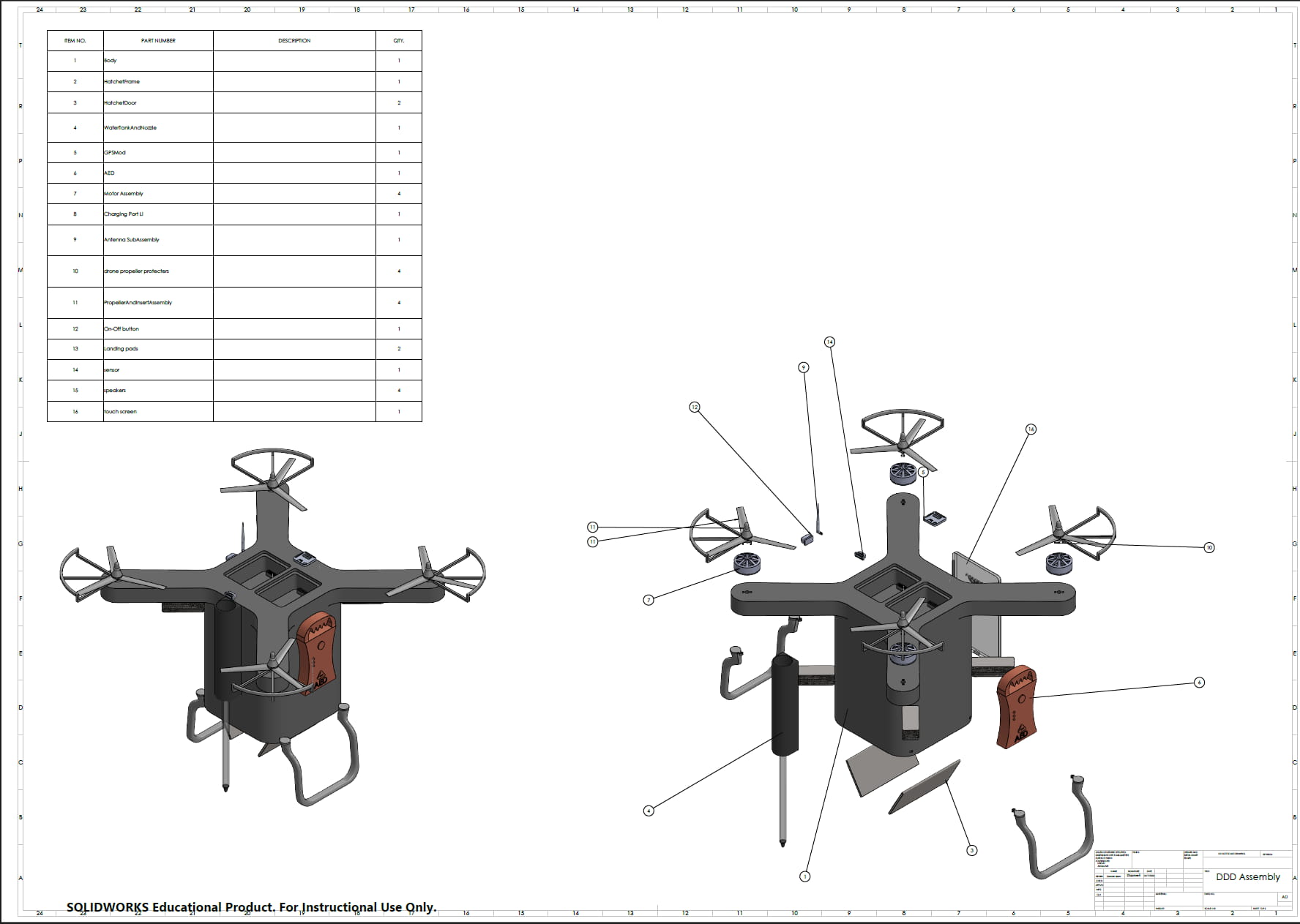
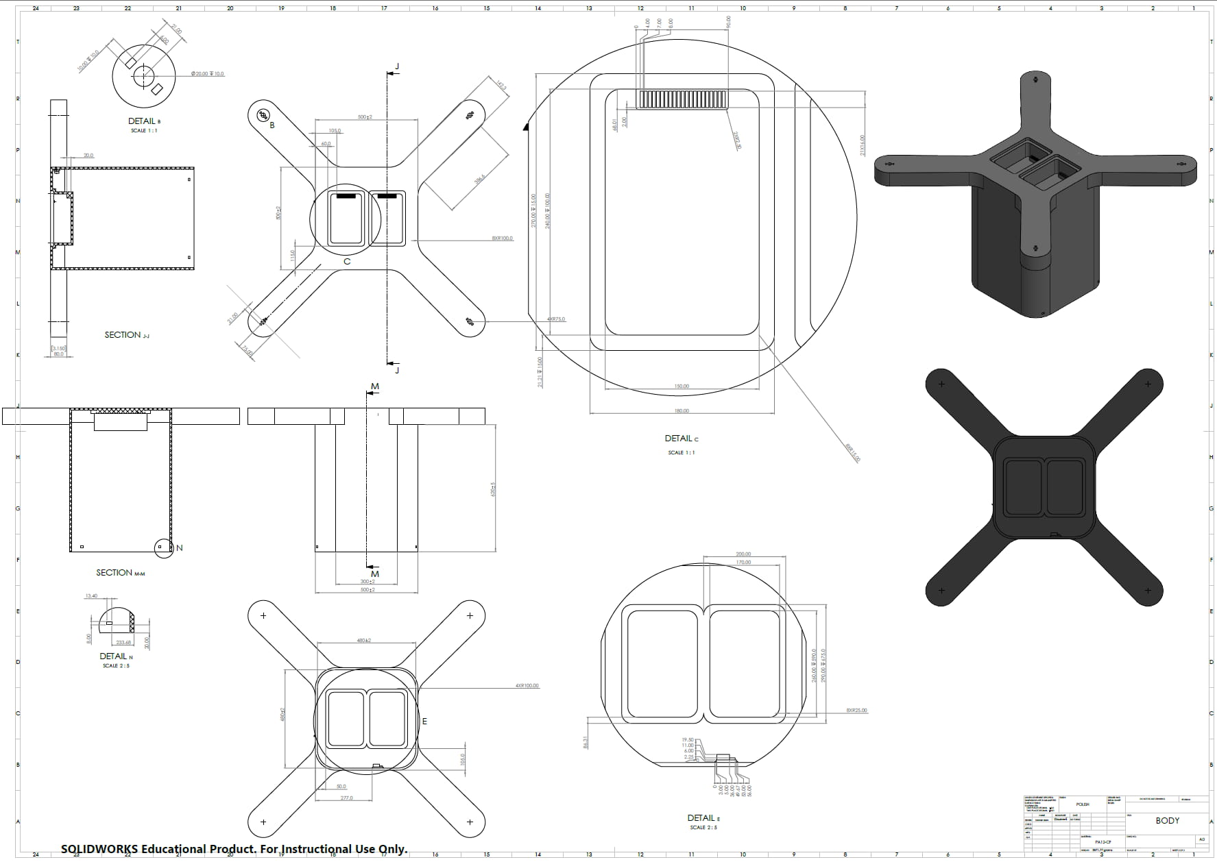
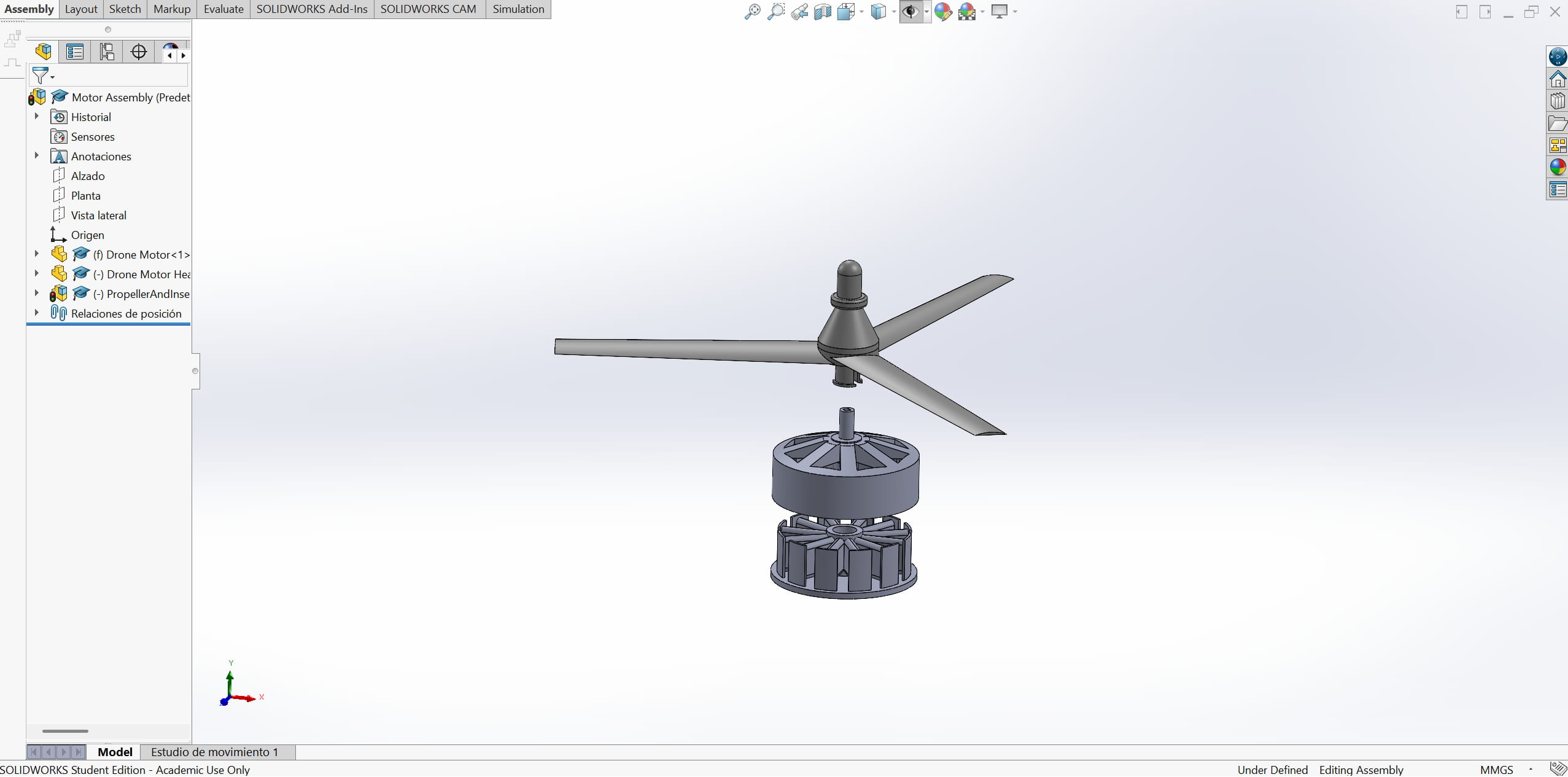
The drone follows a symmetric X-frame layout with four arms extending from a central hub. Each arm terminates in a propeller guard modeled using swept and lofted features in SolidWorks to produce the curved guard geometry. The propellers themselves were modeled as separate sub-assemblies with individual blade geometry defined using surface modeling tools.
The central body houses a dedicated electronics bay with rectangular cutouts for battery and control board mounting, modeled using extruded cuts and shell features to minimize weight while maintaining structural integrity. A payload compartment hangs below the main frame, designed to securely carry a medical package — built using SolidWorks weldments and sheet metal features. Landing gear legs extend from the lower frame, modeled as structural members with filleted joints.
All parts were designed individually and brought together using SolidWorks assembly mates — coincident, concentric, and distance mates — to fully constrain the model. Creo was used for advanced modeling and final presentation visuals.
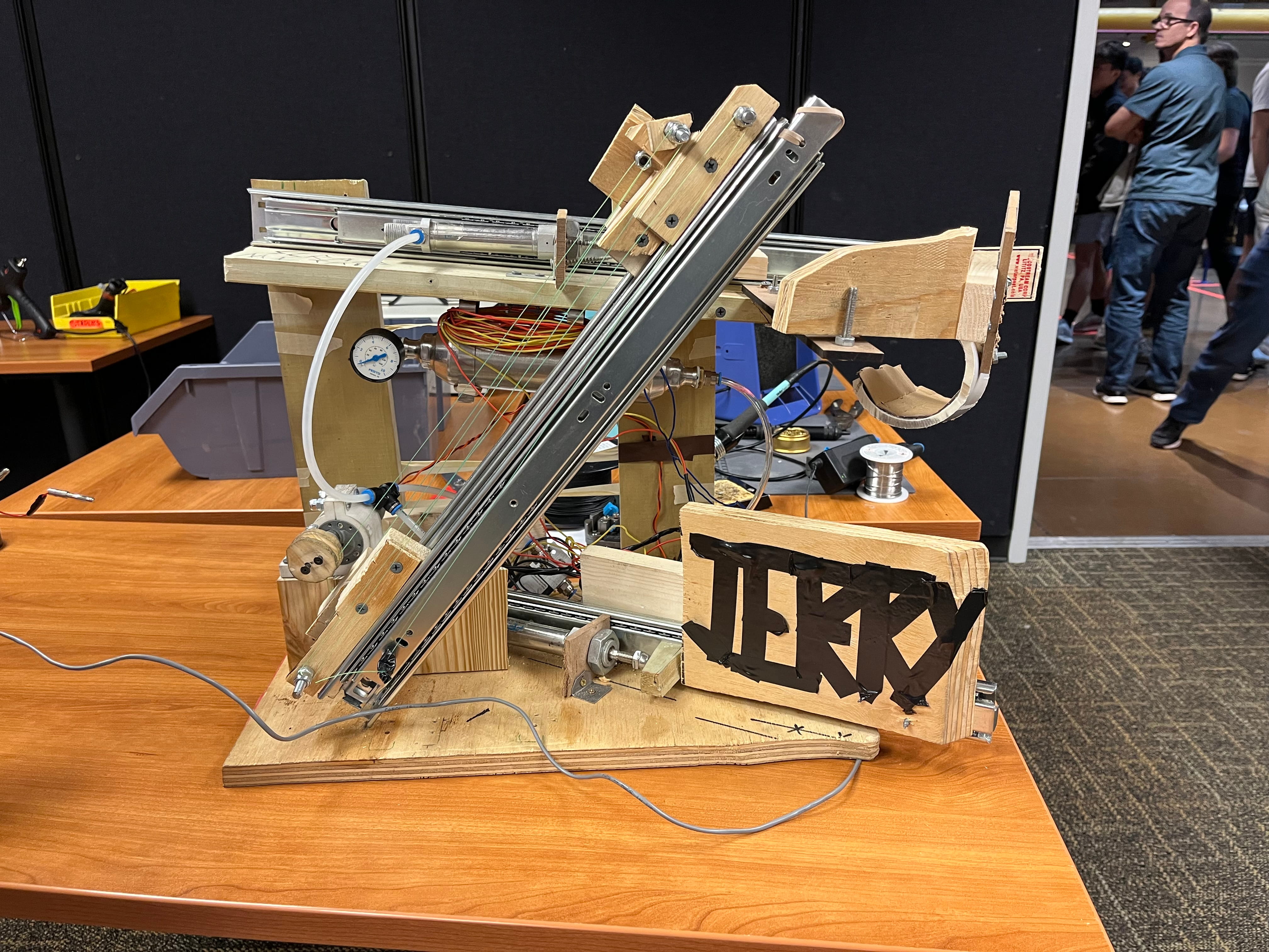
An Arduino-controlled electromechanical robot. Iterative redesign reduced task completion time by 28 seconds.
Open project ↗
ME 2110 — Programmable Robot Design & Build
Georgia Institute of Technology · Atlanta, GA
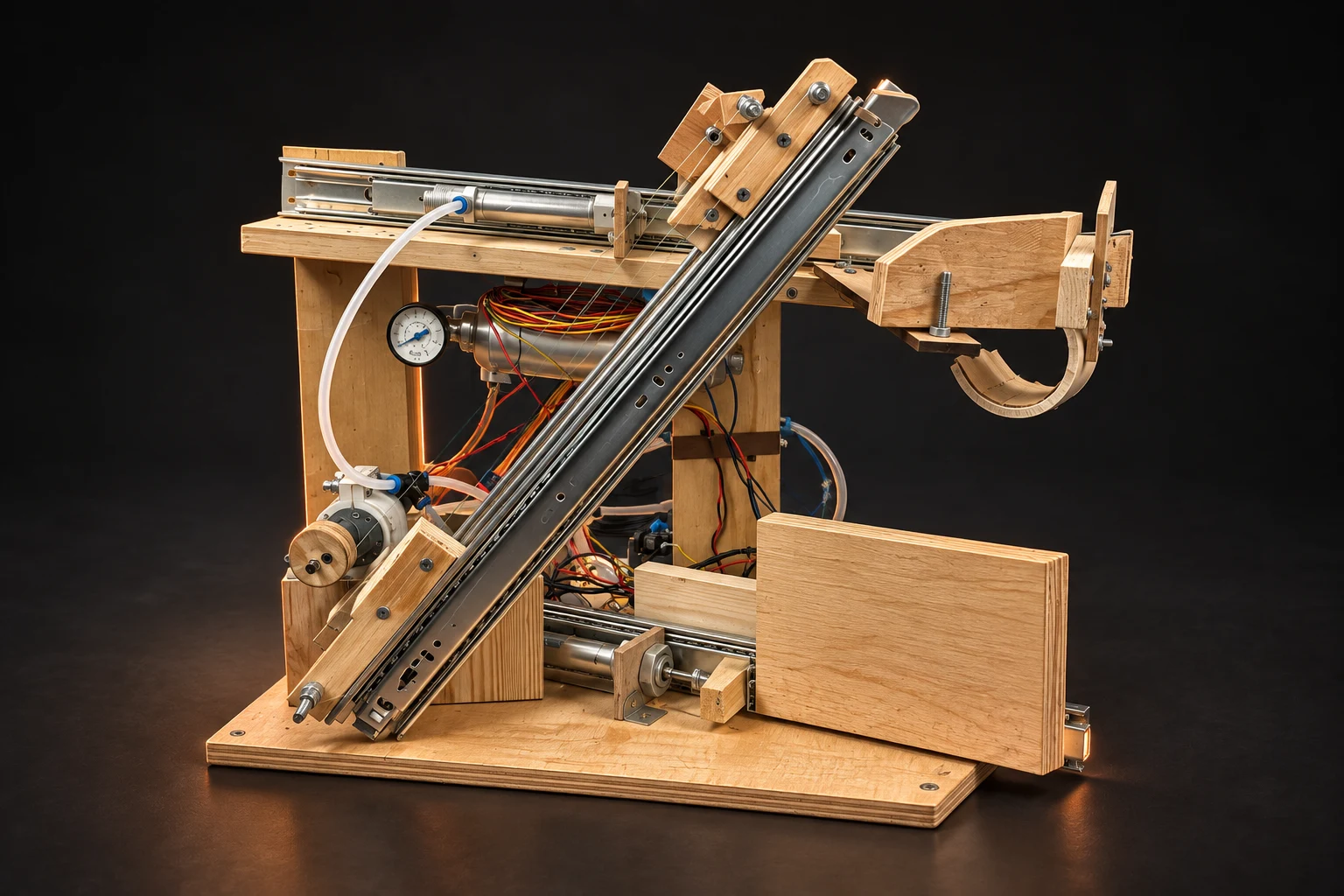
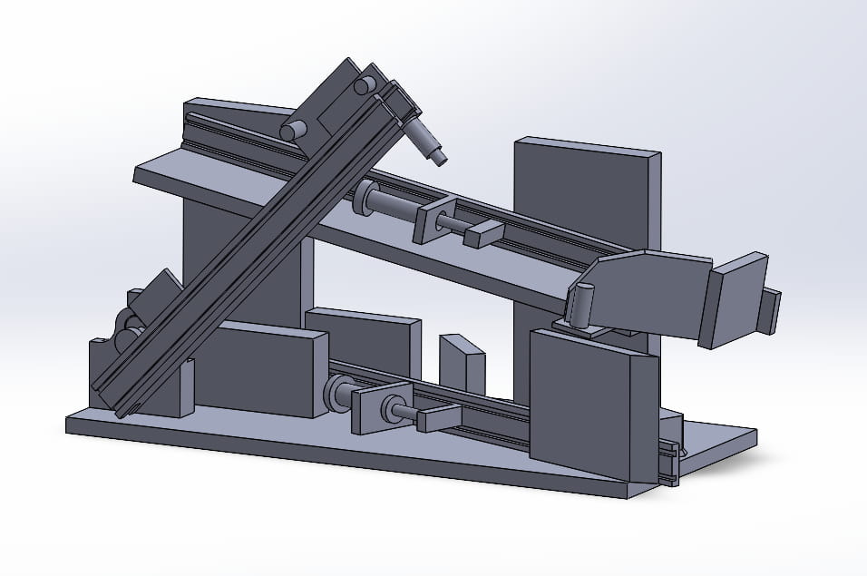
Designed and built a fully programmable robot for a competitive design challenge, integrating DC motors, pulleys, pneumatic pistons, solenoids, encoders, and sensors into a cohesive electromechanical system. The robot was programmed in C++ using Arduino to identify and manipulate objects autonomously, with AC adapters and a pressure tank powering the actuation system. Iterative testing and redesign of the control logic and mechanical layout reduced task completion time by 28 seconds compared to the initial prototype.
SolidWorks CAD — Robot Assembly to Scale
Physical Build — Final Competition Robot
A detailed 3D CAD model of the robot was produced in SolidWorks, with all components drafted to scale to create a precise digital replica used for presentation and documentation. The model captured the full mechanical layout including motor mounts, pneumatic routing, and sensor placement — serving as both a design validation tool and a communication artifact for the team.
Georgia Institute of Technology · ME 4182 · Sponsor: DIU
Senior Capstone Design · Team SolidWorks Doomscrolling
Design and Validation of a Modular Shock Tube System for Transient Pressure Testing
A modular materials-testing concept, developed through SolidWorks modelling, flange-joint calculations, and driver-section FEA.
Open project ↗
Design and Validation of a Modular Shock Tube System for Transient Pressure Testing
Georgia Institute of Technology · ME 4182 · Sponsor: DIU
A four-person senior capstone team developed a modular shock tube concept for DIU to study how materials respond to repeatable transient pressure loads. The work progressed from requirements and concept selection to CAD, pressure-region modelling, component calculations, and a static structural study. The deliverable was a digital design and analysis package; no physical shock tube was manufactured or tested.
My contribution: created all SolidWorks models, performed the bolt calculations and driver-section FEA, and contributed to concept ideation, market research, and the final report. Pressure-region modelling, tube-length analysis, wall-sizing calculations, and intake-system development were team contributions.
01 / Define the test problem
The existing test equipment lacked modular access and convenient instrumentation. The team translated the brief into targets for a 12 ft × 8 ft footprint, a cycle time below 20 minutes, and a pressure-range requirement extending to 2,000 psi. The report recommended operation at or below 500 psi as its initial basis. These were design requirements and recommendations, not demonstrated operating capabilities.
A diaphragm separates the pressurized driver from the lower-pressure driven section. Its rupture sends an incident shock toward the specimen; reflection at the end wall creates a different loading region. The supplied process video introduces this sequence.
Shock tube process — supplied explanatory video
02 / Select and model the modular assembly
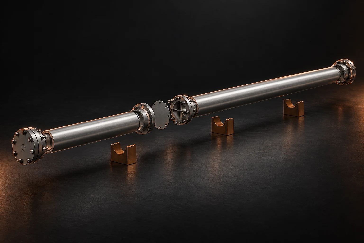
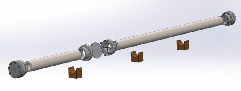
The team compared constant-area, conical, and convergent concepts, selecting a straight, constant-diameter arrangement for its simpler analysis and modular interfaces. I modelled the driver and driven sections, bolted flange collars, diaphragm interface, end plates, and supports in SolidWorks. The assembly separates at the central joint to support diaphragm replacement and internal access; the end-wall concept provides a specimen-mounting interface.
SolidWorks exploded assembly — driver, diaphragm interface, driven section, end plates, and supports · Tap image to enlarge ↗
03 / Establish the pressure model and gas-handling layout
The team used MATLAB pressure-region calculations to compare driver/driven gas combinations and relate incident shock strength to the loading at the test location. This distinguished initial driver pressure from incident and reflected pressures. The ideal-gas incident-shock relation used in the report was:
P2 / P1 = 1 + [2γ1 / (γ1 + 1)] (Ms2 − 1)
Here P1 is the initial driven-gas pressure, P2 is the pressure behind the incident shock, γ1 is the driven gas’s specific-heat ratio, and Ms is the incident shock Mach number. Separate calculations addressed the driver requirement and reflected pressure. The report identifies the maximum end-wall loading assumption as an item requiring further validation.
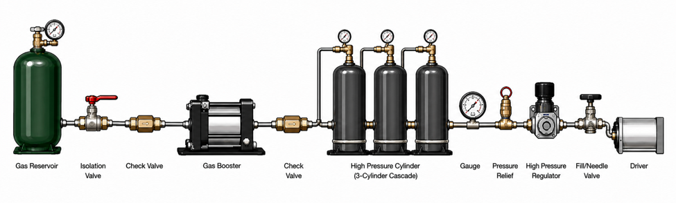
The intake concept combined a reservoir, gas booster, cylinder cascade, regulator, isolation and check valves, pressure indication, and relief protection. A separate exhaust concept addressed gas removal and baseline recovery. These subsystems were considered alongside the access and reset workflow.
Intake concept — gas supply, pressure control, and protective components · Tap image to enlarge ↗
04 / Evaluate the flange joint and driver section
I evaluated the flange joint using the report’s assumed design load and an eight-bolt load split. The calculation below records that preliminary model; final joint design still requires verification of the effective pressure area, preload, sealing, and transient loads.
Fbolt = Fdesign / N = 628.86 / 8 = 78.61 kN
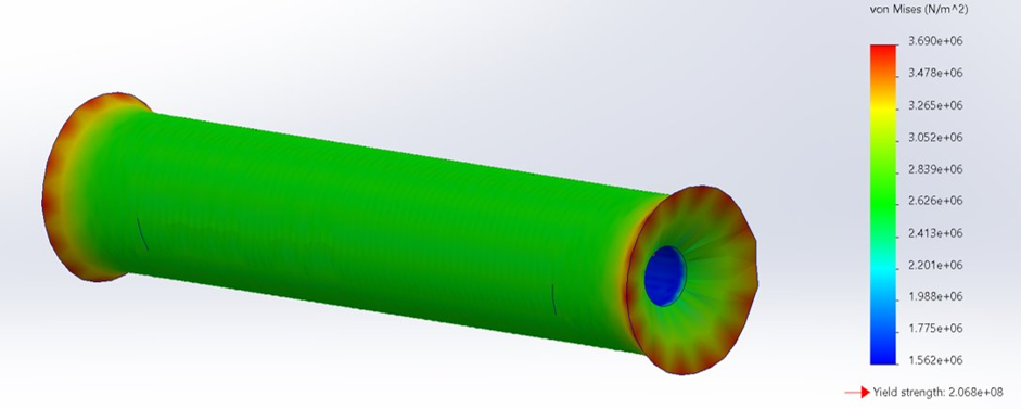
I then ran a static SolidWorks Simulation study of the AISI 304 stainless-steel driver section with 500 psi internal pressure and one end fixed. The reported peak von Mises stress was 3.690 MPa, with concentrations near the constrained end faces. Compared with the assigned 206.8 MPa yield strength, this gives the following yield-to-stress ratio for that model:
Sy / σvM,max = 206.8 / 3.690 ≈ 56
Driver-section static FEA — reported peak von Mises stress 3.690 MPa at 500 psi applied pressure · Tap image to enlarge ↗
This result describes the submitted static model, rather than a validated rating for the complete system. Transient pressure, thermal effects, joint behaviour, and repeated loading were outside its scope. The report also contains conflicting wall-thickness descriptions, which need reconciliation before manufacturing review.
05 / Document the workflow and hand off the design
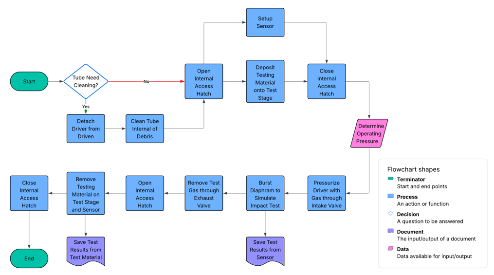
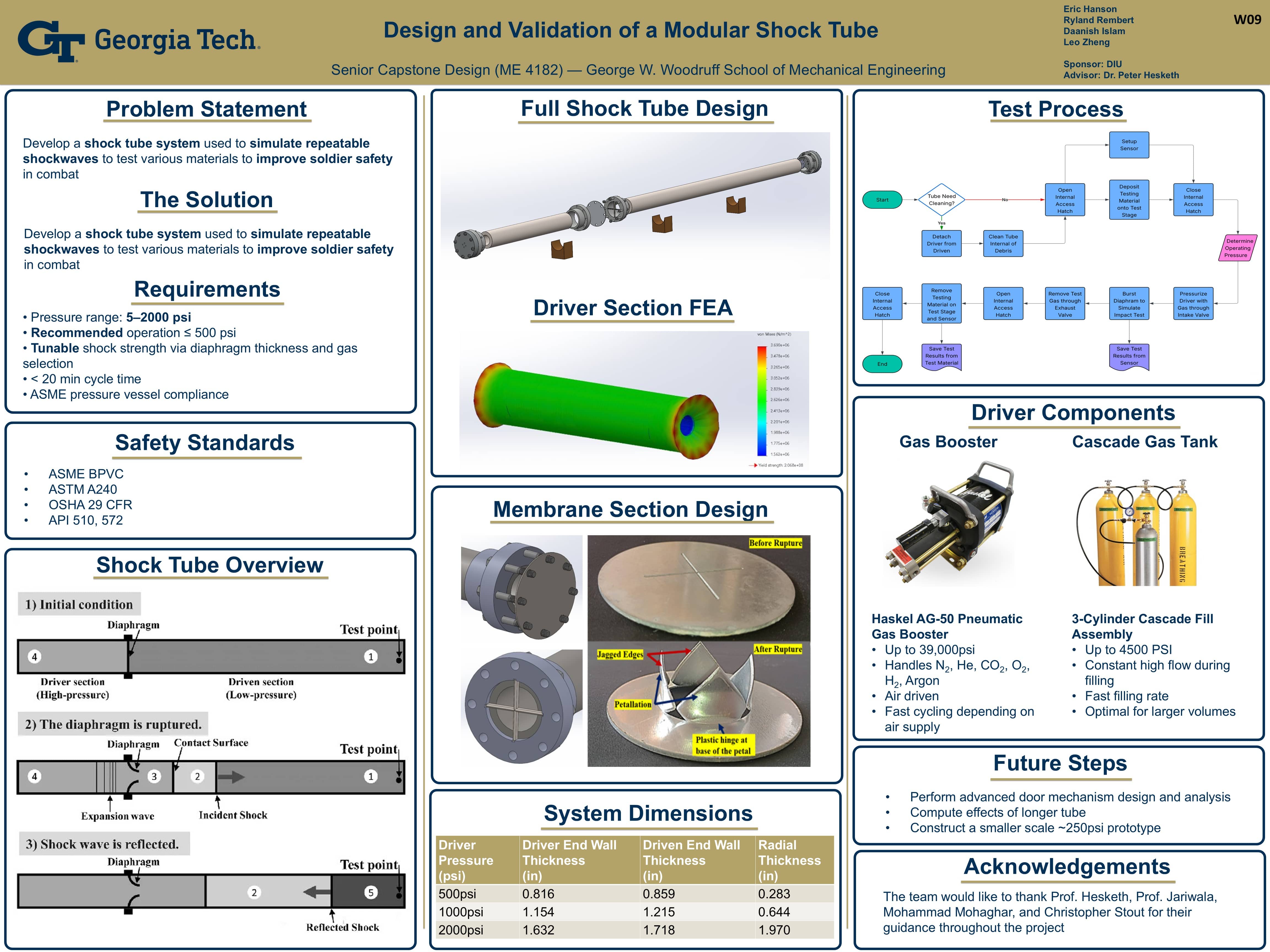
The team mapped specimen and sensor setup, testing, gas removal, sample recovery, and data capture to expose the access and reset steps behind the cycle-time target. The final handoff combined CAD, calculations, subsystem layouts, and an expo poster. Recommended next work included experimental diaphragm characterization, sealing and tolerance review, and coupled thermal-structural analysis.
System block diagram — proposed test and reset workflow · Tap image to enlarge ↗Senior Capstone Design (ME 4182) — final project poster · Tap image to enlarge ↗
500 psi
Static FEA load case
3.690 MPa
Reported peak stress
4
Team members
SolidWorksStatic FEABolted JointsPressure-Vessel AnalysisConcept SelectionModular DesignMATLAB · Team Analysis
I connect mechanical design with controls, fabrication, and system integration.
My work spans industrial robot programming, thermal-spray fixtures, research prototypes, and UAV hardware. I enjoy taking a design through the full cycle: modeling, analysis, fabrication, testing, and iteration.
Aug 2026 — Present
Graduate Teaching Assistant
Woodruff School of Mechanical Engineering · Georgia Tech ME 3057 laboratory instruction, equipment operation, and technical report feedback.

 01PROJECT CONCEPT